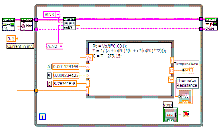
LabVIEW Block Diagram
Select Window->Show Diagram to display the block diagram. Complete the diagram as shown
-
 Insert EMANT300 Read Analog.VI
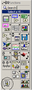
  from Functions palette using Select a VI
Right mouse click to bring up the Functions Palette. Bring your mouse to Select a VI and click on the icon. Go to the Drivers folder and locate the VI library EMANT300.llb Select the EMANT300 Read Analog.VI This VI reads the voltage across the thermistor.
-
From the same VI library, insert the EMANT300 Write IDAC.VI
 This VI sets the current of the 8 bit current DAC
 -
From the same VI library, insert the EMANT300 Initialisation.VI
 and EMANT300 Close.VI
-
Insert Formula Node
 from Functions->Structures palette.
A Formula Node evaluates mathematical formulae and expressions similar to C on the block diagram. This is useful if the mathematics is quite involved and is clearer when implemented in text form rather than in a graphical manner.
To create an input, use the position tool, right click on the left border of the Formula node. Select Add input from the popup menu. Name it Vo. Next right click on the right border of the Formula node. Select Add output from the popup menu. Name it T. Add all the other nodes shown in the diagram. Finally select the Text tool and click on the Formula Node to enter the following formula
Rt = Vo/(i*0.001);
T = 1/ (a + ln(Rt)*(b + c*(ln(Rt)**2)));
C = T � 273.15;
The first line calculates the Thermistor resistance. The next line converts from resistance to temperature in Kelvin and finally converts the temperature from Kelvin to Centigrade.
-
Insert Numeric Constant
 from Functions->Numeric palette. Do the same for the remaining Numeric Constants
 -
To create the Analog Input constants, right click with Wiring tool from the Tools Palette
 and select Create->Constant
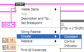
-
When the blank Analog Constant appear, use the Operating tool
 to select the appropriate input channel by clicking on it.
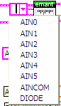
-
Use the Wiring tool from the Tools Palette
to wire the icons as shown in the above block diagram. -
Go back to the Front Panel
-
Click the Run
 button to run the VI. Use the Operating tool to change the High and Low Threshold.
- Observe the ambient temperature
- Use your finger to touch the thermistor. The temperature should change to reflect the higher temperature of your body.
-
Press
 to stop the VI.
 -
Save the VI. Select File->Save. Call the file SARs and Thermistor.vi Close the VI.
End of Exercise 7
Additional Exercises
-
In the US, Fahrenheit is a more common unit of temperature measurement. Modify the VI to allow the user to select the reading in oF or oC.
-
Modify the VI to reflect a temperature limit has been exceeded.
-
It has been found that some people have a normally higher body temperature and therefore a rise in body temperature is a more appropriate indication of fever. Implement this in your program.