The following information is for the EMANT300, EMANT380
Increasing the Range of the Analog Input Voltage
Question:
I connected AIN2 to AGND and AIN3 to the voltage source. The GND of the voltage source is connected to AGND. I am trying to measure voltage from a 5V power supply to the EMANT300.
volt = DAQ.ReadAnalog(Emant300.AIN.AIN3, Emant300.AIN.AIN2)
The device is able to read voltages less than 2.5v but I am unable to read any higher voltage. I wish to read voltages from 0 to 5v.
Answer:
WARNING: If you are using the EMANT380 Bluetooth DAQ, note that the max input voltage with respect to GND is 3.3V and not 5V which is for the EMANT300 USB DAQ. The min input voltage is the same for both at 0V.
Your analog input range required is 0 to 5V whereas the Full-Scale Input Voltage Range of the EMANT300 USB DAQ module is 0 to 2.5V (PGA = 1 VREF = 2.5V Unipolar Input - see EMANT300 specs).
A workaround is to connect the AIN2 to REFOUT (which is 2.5V) instead of AGND and AIN3 is connected to your signal.. If AIN3 goes from 0 to 5 with respect to AGND, then with respect to AIN2 (2.5V) the measured voltage is -2.5V to +2.5 respectively. This also implies that the measurement must be bipolar hence you need
DAQ.ConfigAnalog(2.5, Emant.Emant300.POLARITY.Bipolar, 100)
and to add 2.5V to the measured value to convert the reading to 0 - 5V
volt = DAQ.ReadAnalog(Emant300.AIN.AIN3, Emant300.AIN.AIN2)
volt = volt + 2.5
WARNING: Do not connect your Signal GND to AIN2 and REFOUT. Doing so will damage the EMANT300. Your Signal GND should still be connected to AGND.
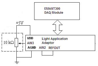
Fig 1: 0 to 5V input signal
Emant3001.Open()
DAQ.ConfigAnalog(2.5, Emant.Emant300.POLARITY.Bipolar, 100)
...
...
volt = DAQ.ReadAnalog(Emant300.AIN.AIN3, Emant300.AIN.AIN2)
volt = volt + 2.5
...
...
Emant3001.Close()
Click High-Voltage-Input.zip to download LabVIEW and C# 2010 examples.
A more general solution to the above problem uses the following schematic. (We are using AIN3 and AIN2 - any analog input pair can be used)
Fig 2: +15V to -15V input signal
Using AIN2 and AIN3, the circuit measures input from +15V to -15V. The voltage is attenuated by 10 so the AIN3 voltage swing is 4V to 1V. The voltage is given by the following equation
Applying the same formula to V AIN2 and since R1 = R3 and R2 = R4 and simplifying, we obtain the following general equation
- The voltage at the inputs should not be less than 0 or greater than 5V to avoid damage to the inputs. See Analog Input Range specification with Buffer On and Buffer Off
- R2 = R4 should not be less than 2K to avoid loading VREF.
- Don't forget to multiply the measured voltage with the inverse of the attenuation factor