Switching loads of up to 3A and 250VAC
Danger - circuit must be encased when operating at high voltages for safety reasons as high voltages can kill. Please do not implement the circuit if you are not sure of what you are doing. You are responsible for your own actions.
The internal circuitry of the EMANT300 DIO (D0..D7) can be shown as below.
When configured as a digital output (DO), the DO can typically sink up to 20mA current. The absolute maximum current is recommended to be no more than 30mA. Also the output voltage should not exceed 5V.
In applications where higher voltages and currents are required, a relay is a solution. In this application note, we have selected the PCN-105D3MHz.
From its specifications, it can switch
- 3A, 250 Vac
- 3A, 30 Vdc
As we are using the 5V version, its coil characteristics are
- Pull in voltage - 3.5V
- Release voltage - 0.5V
- Coil resistance - 208 ohms
- Coil current - 24 mA
As the coil characteristics (eg coil current 24 mA < DO max current 30mA) is within the specifications of the EMANT300 digital output, we can therefore connect the coil directly to the DO.
Finally we must add a freewheeling diode (1N4148). When the coil is turned on, it stores energy. When it is switched off, the voltage across the coil can rise to voltages well above the 5V rating of the DO thereby destroying it. The freewheeling diode placed across the coil provides a path for the release of energy stored in the coil when the coil voltage drops to zero. Please note the direction of the diode. Incorrect orientation will create a short circuit to be seen causing DO to sink current beyond its limit and thereby destroying it.
If you choose another relay and its voltage and current requirements are greater, you will have to use the ULN2003 (7 channel darlington) between the relay coil and the DO to avoid damaging the DO.
For programming, you may use the LED example LabVIEW or Visual Basic program. As the relay is connected to D0, the program that turns on the Green LED will turn on the relay.
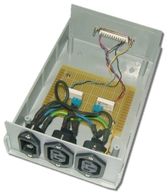
The following photograph shows a 2 relay output circuit encased for safety reasons. The cover has been removed to show the circuit board.