Build the PID Temperature Control circuit
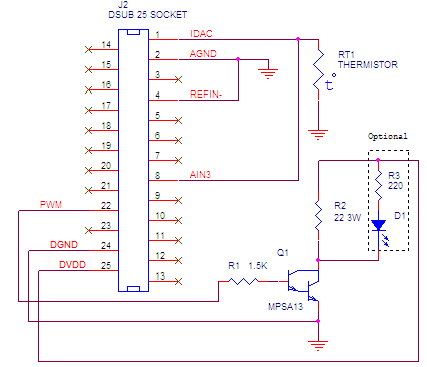
Construct the following circuit either using a solderless breadboard or a protoboard.
Parts List
- R1 1.5K 1/4W resistor
- RT1 Thermistor 10K NTC
- Q1 MPSA13 Darlington
- R2 Heating Resistor 22 ohm 3W
Optional Components
- R3 220 1/4W resistor
- D1 LED

Connection diagram

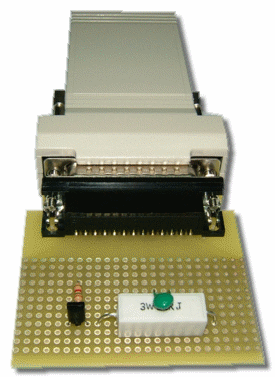
Circuit constructed using ProtoBoard
- DO NOT CONNECT THE EMANT300 TO THE USB PORT YET.
- Connect the components. Take note of the connections for the transistor. Connect the 22 ohm load resistor and thermistor in a way that they make good thermal contact.
- Connect to the EMANT300. If you are using the Light Application Adaptor. PWM, IDAC, AIN3, VDD, GND are available as screw terminals.
Note: If you are using the Light Application Adaptor, REFIN- is already connected to AGND. If you are connecting directly to the EMANT300, it is important that this connection is made, otherwise your analog input measurements will be wrong. This connection allows the internal reference to be connected correctly.
- Connect the EMANT300 to the USB port.
- Open Temperature Control for Hatching Chicks.vi from the PID Temperature Control folder. You will use this VI to verify that your circuit is built correctly.