PID Control Solution
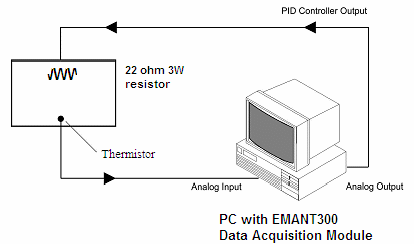
One way to heat up the incubator would be to use a heating element. However, it is difficult to keep the temperature fairly constant using a lamp without some form of control. In our exercise, we will make use of a 22ohm 3W resistor to simulate the heating element.
A basic control solution comprises the following

We measure the temperature using a thermistor and heat up the incubator using a 22 ohms 3W resistor. We will use the proportional (P), the integral (I), and the derivative (D) controls (PID Control).
PID Control
First, let's take a look at how the PID controller works in a closed-loop system using the schematic shown above. The variable (e) represents the tracking error, the difference between the desired input value (R) and the actual output (T). This error signal (e) is sent to the PID controller. The signal (u) output from the controller is equal to the proportional gain (Kp) times the magnitude of the error plus the integral gain (Ki) times the integral of the error plus the derivative gain (Kd) times the derivative of the error.

- Kp = Proportional gain
- Ki = Integral gain
- Kd = Derivative gain
This signal (u) will be sent to the lamp, and the new output (T) will be obtained. This new output (T) will be sent back to the sensor again to find the new error signal (e). The controller takes this new error signal and computes its derivative and its integral again. This process goes on and on.
A proportional controller (Kp) will have the effect of reducing the rise time and will reduce, but never eliminate, the steady-state error. An integral control (Ki) will have the effect of eliminating the steady-state error, but it may make the transient response worse. A derivative control (Kd) will have the effect of increasing the stability of the system, reducing the overshoot, and improving the transient response.
The PID.vi has already been created for you. Go to the PID Temperature Control folder and open PID.vi Study the VI. It is basically our LabVIEW implementation of the above formula.
Thermistor
Thermistors are widely used because of their sensitivity, small size, ruggedness and low cost. Thermistors have an electrical resistance that varies non-linearly with temperature. The Resistance -Temperature characteristics of most thermistors can be described by the Steinhart-Hart equation:
1/T = A + B*(Ln RT) + C*(Ln RT)3
RT is the resistance of the Thermistor, T is the absolute temperature (in Kelvin) and A, B, and C are constants which can be determined by measuring three sets of resistance and temperature values during calibration.
Most thermistors have a negative temperature coefficient (NTC), their resistance decreases with increasing temperature. Thermistors are specified according to its nominal resistance at 25 oC and commonly available thermistors range from 250 ohms to 100 kohms
The thermistor that we are using has the following characteristics
- Nominal resistance @ 25 oC: 10 kohms
- negative temperature coefficient (NTC)
As the DAQ module Analog Input measures only voltage, we will need to provide a current source to convert the resistance to voltage. We will use the 8 bit current DAC (digital to analog converter) and set the current to 100uA.
As the thermistor VI has been already developed and explained in the application note Measuring Temperature using Thermistor, we will use the sub VI Temp Control Thermistor.VI
Heater
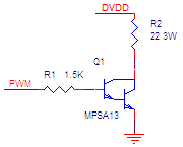
 We will be using a 22ohm 3W resistor to act as the heating element. To reduce the heat from the electronics, we will drive the resistor by PWM (Pulse Width Modulation) using a darlington NPN transistor.
A PWM circuit works by making a square wave with a variable on-to-off ratio; the average on time may be varied from 0 to 100 percent. In this manner, a variable amount of power is transferred to the load.
The main advantage of a PWM circuit over a power amplifier is the efficiency. At a 50% level, the PWM will use about 50% of full power, almost all of which is transferred to the load.
The darlington transistor is used over a regular NPN transistor to reduce the current output requirement of the digital output.